
 Email: sales@slxytech.com
 WhatsApp / Wechat:8617062388866
 Phone:+86 17062388866
Description
| Product Model | 135137-01 |
| Manufacturer | Bently Nevada (a division of General Electric) |
| Product Category | Vibration Monitoring Relay Output Module |
| Core Function | Alarm and Trip Relay Output Interface |
| Input Compatibility | Designed for use with Bently Nevada 3300 Series Monitoring Systems |
| Output Type | Electromechanical Relay Contacts |
| Number of Channels | Multiple relay channels for alarm/trip signal routing |
| Relay Contact Rating | Typically up to 5A at 250V AC or 30V DC |
| Mounting Type | Panel mount or DIN rail mount |
| Operating Temperature | -20°C to +70°C |
| Power Supply | 24 VDC (external or via system backplane) |
| Standards Compliance | IEC 61010, CE, UL, CSA, ISA 82.02 |
Product Introduction
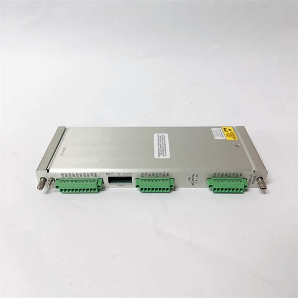
The Bently Nevada 135137-01 is a critical component in industrial vibration protection systems, specifically designed for integration into the Bently Nevada 3300 Series Monitoring System.
This module functions as a relay output interface, converting digital alarm signals from vibration monitoring modules into physical relay closures or openings. These contacts are used to trigger external devices such as emergency shutdown circuits, alarm annunciators, and turbine trip mechanisms when predefined vibration thresholds are exceeded.
Engineered for reliability and durability, the 135137-01 ensures safe and accurate response in applications involving rotating machinery like turbines, compressors, pumps, and generators. It provides galvanic isolation between the control system and field devices, enhancing safety and protecting against electrical interference.
Designed for ease of installation and maintenance, the 135137-01 supports flexible mounting options and integrates seamlessly into both new and existing plant protection architectures.
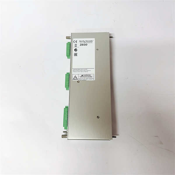
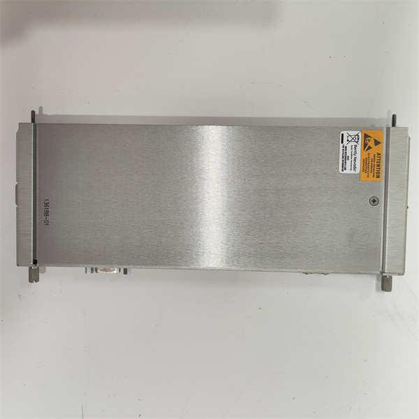
BENTLY 135137-01
Main Features and Advantages
High-reliability electromechanical relays: Built to withstand repeated switching operations and harsh industrial environments, ensuring long-term performance in mission-critical applications.
Galvanic isolation: Provides electrical separation between internal electronics and external devices, protecting both the monitoring system and connected equipment from surges or faults.
Customizable alarm/trip responses: Can be configured to respond to various alarm levels (e.g., Alert, Danger), allowing for tailored machine protection strategies.
Compatibility with 3300 series systems: Designed to work seamlessly with Bently Nevada 3300/10, 3300 XL, and 3300 MMS monitoring platforms.
LED status indicators: Offers visual diagnostics for power, relay status, and fault conditions, enabling fast troubleshooting and minimizing downtime.
Industrial-grade construction: Operates reliably across a wide temperature range (-20°C to +70°C) and resists mechanical shock and vibration typical in industrial settings.
Application Areas
The Bently Nevada 135137-01 plays a vital role in safeguarding rotating machinery across multiple industries:
- Power Generation Plants: Steam turbines, gas turbines, generator sets
- Oil & Gas Industry: Centrifugal compressors, pipeline pumps, offshore platforms
- Petrochemical and Refining Facilities: High-speed centrifugal machines, process pumps
- Marine Propulsion Systems: Turbine-driven propulsion units and auxiliary generators
- Mining and Heavy Industries: Large fans, mills, and material handling systems
In these environments, the 135137-01 ensures that excessive vibration or other mechanical anomalies result in timely alarms or automatic shutdowns, preventing catastrophic failures and extending equipment life.
Related Products
- Bently Nevada 3300/10 Monitor: Base unit for 3300 series systems, providing real-time vibration monitoring.
- Bently Nevada 3300 XL Proximity Transducer: Measures shaft vibration and position for use with 3300 systems.
- Bently Nevada 3300/52M Multi-Machine Monitor: Expands system capability by supporting multiple monitored machines.
- Bently Nevada 3300/20 Dual Channel Monitor: Processes two independent vibration channels before triggering relays.
- Bently Nevada 39953-01 Mounting Bracket: Optional mounting hardware for DIN rail installation of the 135137-01.
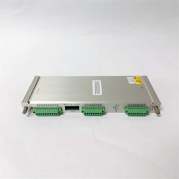
BENTLY 135137-01
Installation, Commissioning, and Maintenance Instructions
✅ Installation Preparation
- Ensure all power sources are disconnected before installing the 135137-01.
- Verify that the panel or DIN rail is clean, secure, and suitable for industrial use.
- Use proper ESD precautions when handling the module.
- Review wiring diagrams and ensure terminal blocks match your system configuration (alarm, danger, trip, etc.).
⚙️ Commissioning Steps
- Securely install the 135137-01module in the designated location (panel or DIN rail).
- Connect the 24V DC power supply and verify LED indicators for correct power-up.
- Wire input signals from the 3300 series monitor to the appropriate terminals.
- Connect output relays to external devices (PLC, SCADA, trip solenoids, alarm lights).
- Test each relay channel individually to confirm proper operation and timing.
- Integrate with higher-level systems and validate alarm/trip logic under simulated conditions.
? Maintenance Suggestions
- Regularly inspect the 135137-01for signs of overheating, corrosion, or loose connections.
- Clean dust and debris buildup periodically to maintain thermal performance.
- Perform functional testing of relay outputs every 6–12 months or as per plant maintenance schedule.
- Replace any damaged or degraded relays promptly to avoid false trips or missed alarms.
- Keep spare modules on hand to minimize downtime during unexpected failures.